@

Saturday, March 12, 2011

how to replace heater core on 1995 thunderbird?

The instructions from 1993 to 1999 is near to same:----------------------
HEATER CORE Removal & Installation 1. Disconnect negative battery cable. Remove instrument panel. See INSTRUMENT PANEL. Remove A/C evaporator housing assembly. See A/C EVAPORATOR HOUSING ASSEMBLY. 2. Remove heater core access cover from A/C evaporator cover housing. Remove tube gasket from heater core tubes. Slide heater core and seals from housing. To install, reverse removal procedure. INSTRUMENT PANEL Removal 1. Disconnect negative battery cable. Disable air bag system. See the AIR BAG RESTRAINT SYSTEM article in the ACCESSORIES/SAFETY EQUIPMENT section. Disconnect underhood wiring at left side of firewall. Working inside vehicle, disengage wiring connector from left kick panel. Carefully pull wiring harness into passenger compartment. Remove both kick panels. Remove radio antenna stanchion bolts. Disconnect radio antenna cable from base of antenna. 2. Remove steering column lower trim cover by removing 3 screws at bottom. Pull trim panel to disengage 3 snap-in retainers across top. Remove 4 screws attaching steering column lower opening reinforcement panel. Remove steering column upper and lower shrouds. 3. Disconnect A/C evaporator register duct from under steering column tube. Disconnect wiring from steering column. Remove shift interlock switch. Disconnect steering column pinch bolt. Support steering column, and remove 4 nuts retaining column to support. Remove steering column from vehicle. 4. Remove screw retaining left side of instrument panel to parking brake bracket. Disconnect pedal assembly wiring. Pull carpet back on both sides of dash and disconnect all wiring connectors with wiring leading into instrument panel. 5. Install steering column lower opening reinforcement using 4 screws (one on each corner). This procedure prevents instrument panel from twisting during removal from vehicle. Remove console assembly from vehicle. Remove 2 screws retaining console glove compartment to floor tunnel. Remove 2 screws retaining front of console to instrument panel. Remove console assembly. 6. Open glove box, squeeze sides of bin and lower box to full open position. Remove glove box assembly. From underneath instrument panel and through glove box opening, disconnect wiring and A/C-heater vacuum lines and control cables. Remove nut at right retaining instrument panel to cowl side. Remove 2 nuts at left retaining instrument panel to cowl side. Remove 2 nuts and one bolt to console bracket. 7. Remove right and left upper finish panels by pulling up to disengage snap-in retainers. Remove 6 bolts retaining instrument panel to cowl top. Remove right and left door rail trim panel. Remove door frame weatherstrip. 8. Carefully pull instrument panel away from cowl, and disconnect any remaining wiring or controls. Remove instrument panel from vehicle. Installation To install, reverse removal procedure. Steering column opening lower reinforcement must be installed on replacement panel before installing in vehicle. A/C EVAPORATOR HOUSING ASSEMBLY NOTE: If an A/C evaporator leak is suspected, evaporator core must be leak tested BEFORE removal. See LEAK TESTING in the A/C SYSTEM GENERAL SERVICING article in the A/C SYSTEM GENERAL SERVICING section. Removal 1. Disconnect negative battery cable. Remove instrument panel. See INSTRUMENT PANEL. 2. Discharge A/C system using approved refrigerant recovery/recycling equipment. Remove high and low pressure hoses. Disconnect liquid line and suction accumulator-drier at evaporator. See REFRIGERANT LINES. Plug all openings to prevent contamination. Remove suction accumulator-drier. See ACCUMULATOR-DRIER. 3. Remove throttle cable bracket and position aside (if necessary). Disconnect heater hoses from heater core tubes, and plug hoses and heater core tubes. Disconnect vacuum supply hose from the in-line A/C vacuum check valve. 4. Remove 3 evaporator assembly bolts from engine compartment side of firewall. In passenger compartment, remove screw attaching evaporator assembly support bracket to the top cowl panel. Remove one nut securing the bracket below A/C evaporator housing assembly to dash panel. Remove one nut retaining mount bracket at left end of evaporator housing to dash panel. Carefully pull assembly from dash panel and remove from vehicle. Installation To install, reverse removal procedure. Use NEW "O" rings lubricated with refrigerant oil. Evacuate, recharge and leak test system. See EVACUATING A/C SYSTEM, CHARGING A/C SYSTEM and LEAK TESTING in the A/C SYSTEM GENERAL SERVICING article in the A/C SYSTEM GENERAL SERVICING section. REFRIGERANT LINES Removal & Installation 1. Discharge A/C system using approved refrigerant recovery/recycling equipment. To remove refrigerant lines, fit appropriate spring lock coupling clamp on line. See SPRING LOCK COUPLING CLAMP table. See Fig.
Close clamp, and push it into opening side of cage to expand garter spring and release female fitting. After garter spring is expanded, pull coupling apart. 3. To install, lubricate fittings with clean refrigerant oil and install NEW "O" rings. Push couplings together using a slight twisting motion. Ensure garter spring is over flared end of female fitting. SPRING LOCK COUPLING CLAMP Refrigerant Line Diameter Part Number 3/8" T81P-19623-G1 1/2" T81P-19623-G2 5/8" T831P-19623-C 3/4" T85L-19623-A ACCUMULATOR-DRIER Removal 1. Discharge A/C system using approved refrigerant recovery/recycling equipment. On 3.8L EFI base engine, disconnect suction hose at compressor. Cap suction hose and compressor to prevent entry of dirt and moisture. On all other models, disconnect suction hose at suction accumulator-drier. 2. On all models, disconnect accumulator-drier inlet tube from evaporator core outlet. Disconnect wire harness connector from clutch cycling pressure switch located on top of accumulator-drier. Remove screw holding suction accumulator-drier to accumulator bracket, and remove suction accumulator-drier.

see fig:--


Installation To install, reverse removal procedure. Use new "O" rings lubricated with clean refrigerant oil. Evacuate, recharge and leak test system.


Dashboard Disassembly and Removal

The first and most important step when removing the dash is to disconnect the battery and wait 5 minutes for the airbag battery backup to run down. Set your parking brake since you will need to move the shifter out of Park for clearance.

Start by removing the center console. If you lift up the lid of the console you will find 2 screws in the back edge of the console trim; remove them.

Next lift up on the console piece you just removed the screws from; there are several clips holding it in place as well as a wiring harness powering the lighter. Note the trans will need to be in 1st for proper clearance to remove.


Lift the lid again and remove the rubber liner from the bottom of the storage bin, underneath you will find 4 screws; remove them.

Next remove the 2 screws holding the front of the console to the dash as well as the 2 screws on the front sides of the center console hidden under the plastic caps. Last but not least remove the 1 screw in the center behind the shifter.

Next disconnect the wiring harnesses that power the trunk release, gas cap release etc.

Lift console out and set aside.

For the next steps I found it easiest to first remove the drivers seat. There are 4 bolts holding the seat track to the floor.

Remove the panel under the steering column; it is secured with 3 bolts at the bottom and clips at the top. Once you have the bolts removed pull the panel back toward you not down.

Now remove the AC duct under the steering column; it is secured with 1 screw.

Remove the 3 screws securing the steering wheel shroud and unscrew the tilt lever.

Remove the ignition switch lock cylinder by inserting your key, then push in the release pin on the underside and pull straight out. Now the upper shroud will come off.

Disconnect harnesses at the base of the steering column. There are 4 snap connectors and one main one secured with a bolt.

Remove the pinch bolt attaching the steering column to the lower yoke and use a screwdriver to slightly spread the joint.

While supporting the steering column remove the 4 retaining nuts; be careful not to drop the column on your head.

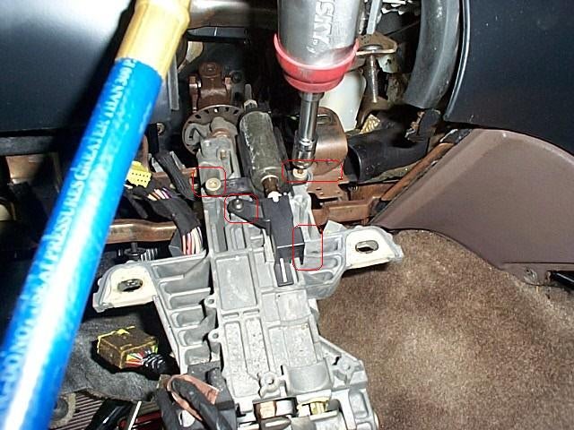
Now with the column lowered remove the shift interlock cable. Note these 4 screws are star type.

Gently remove the column from the car being especially careful not to rotate the wheel.

Disconnect the main harness just above the emergency brake bracket and also disconnect the wires leading to the brake light switch.

Remove the trim panels from around the gauges and around the radio.

Disconnect the main wiring harness at the firewall on the driver’s side by undoing the bolt and pulling the connector backwards. Release the 3 clips holding the other portion of the connector to the firewall and push into the interior.

Remove the kick panels on the driver and passenger sides as well as the trim on the pillars.

Next using a screwdriver carefully pry up on the defroster panel until all the clips holding it are released. Unplug the sunlight intensity meter and remove defroster panel from the car.

Open the glove box and release the piston holding it on the outer edge then remove the 3 screws securing it to the dash and set it aside.

Unplug and remove the EEC and disconnect the harnesses around it behind the kick panel.

Unplug the harnesses and vacuum connector running to the climate controls.

Remove the 8mm bolts underneath the defroster panel. Be VERY careful not to hit the windshield with your wrench. Consider wrapping it in a rag or towel as a precaution.

Remove the 5 nuts at the bottom of the dash.

2 on the driver’s side

1 on the tunnel above the gas pedal

1 in the center section below the radio

1 on the passenger side

Now you need a friend to help. Lift and pull back on the dash until it is 6” – 12” away from the firewall.

You can now get to any remaining harnesses behind the dash and also the radio antenna. Once you disconnect any remaining wiring you can carefully remove the dash and you will be left with something that looks like this.

Replacement is simply the reverse of what you just did.

Heater Core Removal and Replacement

Sir William’s instructions for removing the heater core without discharging the AC worked like a charm. Consider buying new hoses to run to the heater core since it is sometimes easier to cut the old ones out of the way.

Remove the actuator door motor and heater core access panel.

Using a frameless hacksaw cut the heater core tubes as close to the firewall as possible. Believe it or not this was one of the tougher steps in the whole process.

Pull the old core out through the access panel.

Make sure to clean heater box where the core came out good; it will be plenty messy in there. Next cut a slit in the foam rubber gasket in the firewall starting at the hole closest to the center of the car through to the other one and continuing to the outer edge of the opening. I found this easiest to do by sticking my hand inside the heater core access area but I have small hands and others may find it easier to cut from the engine compartment side. Now you can just push the new core in and through the firewall. Replace the access panel and blend door actuator motor.

What comes next is VERY important unless you want to be doing this job over again soon. Ford now recommends that a grounding strap be added to the core to prevent the aluminum from breaking down due to electrolytic corrosion. The TSB specifies copper but I have a problem with that since aluminum + copper + moisture = a battery and the copper would tend to wear away the aluminum where the two are in contact. With that in mind it is advisable to use pre tinned copper wire or if you can’t find any tin it yourself by coating the end that will be in contact with solder.

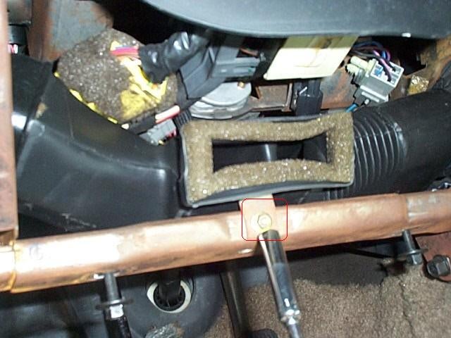
Clamp one end of the grounding strap to one of the heater core tubes and then attach the other end to an existing bolt on the firewall.

Refill your cooling system and you are good to


If the images are not seen full or not very clear or any lines getting cut and not read properly,then please click the link below:----

http://members.tccoa.com/timb/Heatercore.htm


@